Introduction to photovoltaic systems and charge controllers
The future for sustainable energy of human civilization is mainly involved with solar cells. Photovoltaic technologies are employed to convert solar energy into electricity and support their working principles. Variety of applications are considered for solar systems such as wind turbines, street lights and so on. Recent technology advances attract the researchers’ attention to improve applications of solar photovoltaic systems, for example, cellphones which can be charged by solar energy or hybrid cars charging by solar panels instead of gas or diesel energies. Global warming and climate changes mainly restrict the usage of fossil fuels and demand the governments to employ solar systems and their applications. Although fossil resources are not exhausted yet, the advantages of solar systems and environmental impacts of fossil fuels are prominent features to employ clean energy resources.
Alexander Edmond Becquerel first observed the ability of some specific materials to absorb the power of sun rays in 1839. In 1881, Charles Fritts created the first commercial solar panel. However, these panels were not efficient enough but in 1939, Russell Ohl created the basis for modern solar panels which leads to first viable silicon solar cell design by Bell Labs in 1954.
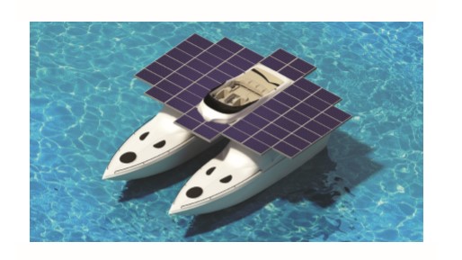
Figure 1- solar panels and photovoltaic applications
Photovoltaic systems are consisted of different components, including solar panels to absorb and convert the sunlight to electricity, a solar inverter to convert DC current to AC one, solar charge controllers to charge the battery and other electrical accessories to set up a working system.
Charge controllers and their impacts on the system’s overall performance are discussed in this article. Charge controller or charge regulator is a voltage or current regulator to protect batteries from overcharging. The voltage or current coming from the solar panel should be regulated before connecting to the battery. The charge controller is employed to regulate voltage/current of the solar panel. Generally, low power panels (1 to 5 watts) do not need a charge controller, so for small maintenance or trickle charge panels, charge controllers are not necessary.
In standalone PV systems, charge controller manages the energy flow to system, batteries and loads by collecting information about the restrictions and maximum and minimum energy inquiries of systems’ components. Different types of charge controllers and their characteristics will be discussed in detail in the coming sections. Pulse width modulation (PWM) and maximum power point tracking (MPPT) solar charge controllers will be investigated through different climate and environmental conditions.
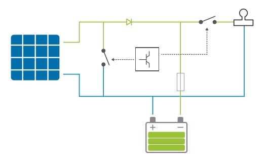
Figure 2-overall view of a charge controller
Maximum power of solar can be determined by the I-V curve of it. Where for zero voltages the maximum current (Isc) and for zero current the maximum voltage (Voc) are applied in a photovoltaic system. Charge controllers are employed to optimize the output power of the PV system so that it ensures the maximum produced energy. Figure 3 illustrates the relation between voltage and current of a PV system (I-V curve).
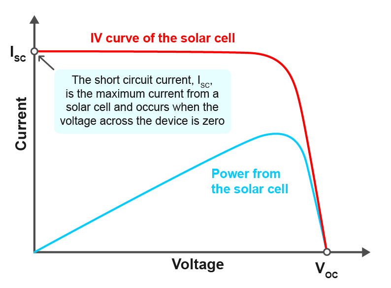
Figure 3- I-V curve of a solar cell
PWM and MPPT charge controllers
PWM (Pulse Width Modulation)
Older charge controllers were mechanically controlling the energy flow to batteries by electric relays but modern charge controllers use PWM to slow down the energy transfer rate to the battery until it will get fully charged. PWM charging mode can be understood as a series electronic switch (MOSFET) in the circuit between PV panel and battery. PWM waveform is generated by the microprocessor to control the on-off and on-off of electronic switch, so as to control the average charging current from PV panel to battery and achieve the average charging voltage of the battery. The schematic diagram of the PWM controller is demonstrated in Fig. 4.
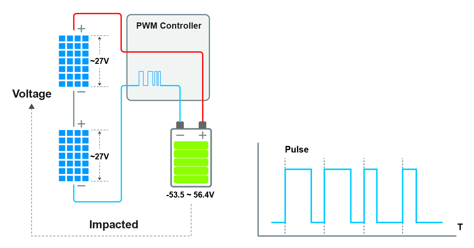
Figure 4-PWM controller and Pulse waveform
In later sections, the I-V characteristics of PWM charge controllers will be discussed in detail. Due to the sharp pulses used in PWM charge controllers, noise problem should be noticed for applications such as TVs or radios where it would cause interferences in their operation.
While charging with a PWM charge controller, the solar panel voltage will lower down to the battery voltage (slightly higher). By turning ON and OFF the MOSFET, the PWM charge controller connects and disconnects the solar panels to the batteries. In most cases, the charging frequency of the PWM controller will be between 25Hz to 100Hz, mainly 50Hz.
So for PWM controller, the charging current is slightly lower than Isc (We can find it from V-I curve of PV panel), at the same time, the working voltage of PV panel is equal to battery voltage. So its charging power is slightly lower than Isc*Vbat. So if we don’t know which size PWM controller suit to the PV panel, we just need to ensure that the Isc of PV array is not higher than the rated charging current of controller. Of course, we should ensure the Voc of the panel not to be higher than the maximum voltage of the controller.
MPPT (Maximum Power Point Tracking)
Novel MPPT controllers are more efficient than primary discussed controllers and are the ultimate in the controller’s design. They match the output of solar panels to the battery voltage to ensure maximum charge. The MPPT is an indirect connection between the solar panel and the battery which consists of DC/DC voltage converter to excess higher current values with lower voltage supplies to get the maximum energy transfer. Maybe the price of these types of controllers is considered as a downside for them but the efficiency in the range of 94%-98% can explain the importance of such controllers while for larger systems they may lead to saving a noticeable amount of money since they provide 10% to 30% more power to the battery.
For example, a 160 watts rated solar panel won’t get the full power until its battery reaches the optimum voltage. With a regular PWM, charge controller battery will receive a limited amount of power as the voltage of the input array is limited to the batteries voltage and there are no regulations on the current. This is while for an MPPT charge controller, the current is regulated so that for a certain amount of voltage, there is a rise in the rate of current, so the maximum power from solar panels will be available for the storage system. This mechanism prevents up to 30% power loss of the ordinary charge controllers.
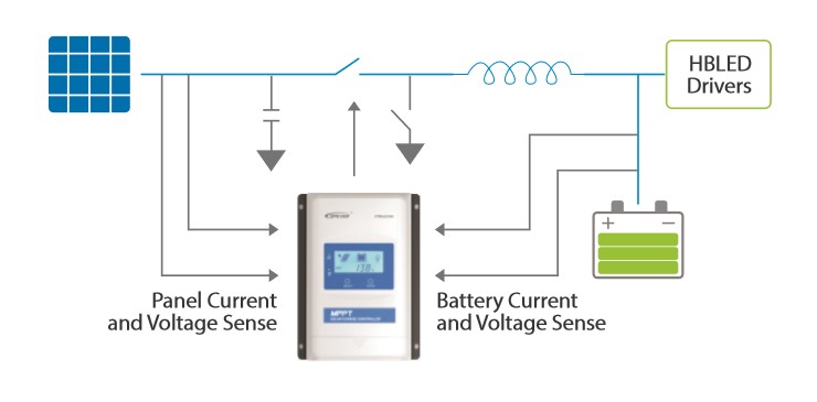
Figure 5- working principle of the MPPT charge controller
Let’s discuss the working principle an MPPT charge controller; where the MCU as a brain of the structure controls the whole circuits including sampling and driver circuits, communication and so on. MCU is supplied by a 3.6V battery while the circuit supplied by 12 V and a 5V voltage for communication is provided. The sampling circuit gathers the voltage, temperature of PV, battery and load and sends a signal to MCU to process the data and start the charging process. The multi-charging function is also provided through driver circuit which governs the MOSFET to switch on/off.
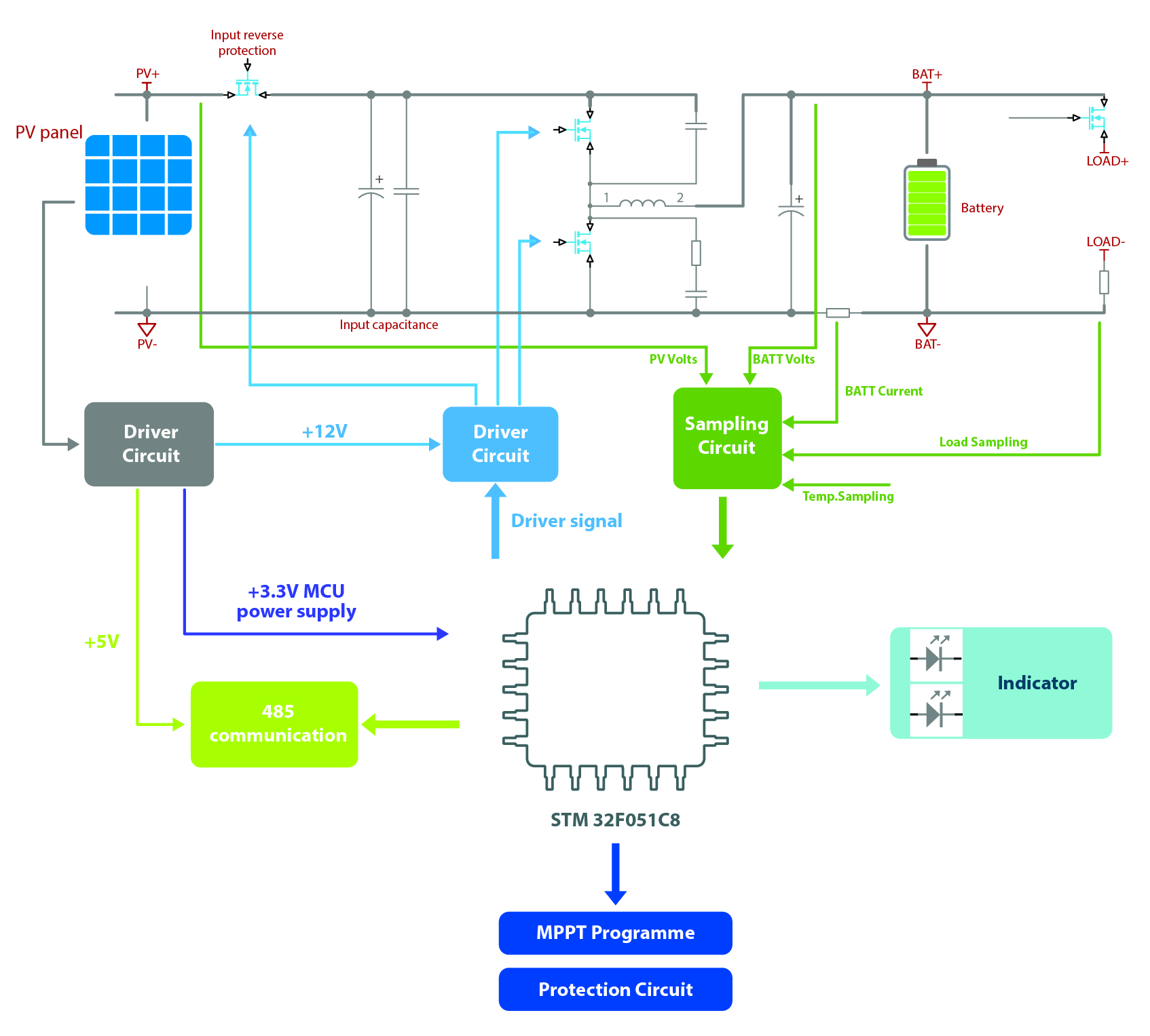
Figure 6- MPPT charge controller schematics diagram
When MOSFET is working the voltage of PV should be a square wave with an operating frequency of 40 kHz to charge the battery. The MOSFET determines the average voltage of PV by its duty cycle. The capacitors demonstrated in the schematics diagram are employed to store energy and stabilize the voltage. The quality and size of the capacitors determine the ripple so the smaller the ripple, the better performance and efficiency of the charging process. When the MOSFET is on the capacitors and PV charging the battery together while when the MOSFET is off the PV still charging for the capacitors. This will cause small fluctuations in the PV voltage which is illustrated in Fig. 7.
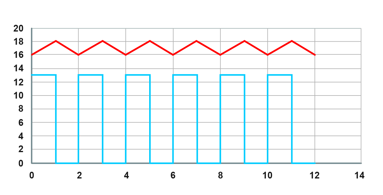
Figure 7-Diagram of the PV voltage
I-V characteristics of solar charge controllers
In this section, the characteristics of photovoltaic systems will be discussed through the I-V curve of solar charge controllers. The operation of proposed charge controllers is explained by the equivalent circuit model. The charge process and optimum voltage for controllers are achieved through I-V curve analysis. The voltage and current of the solar panel can be detected through the I-V curve. Various operation conditions with less efficiency and the application of charge controllers are obvious with the I-V analysis.
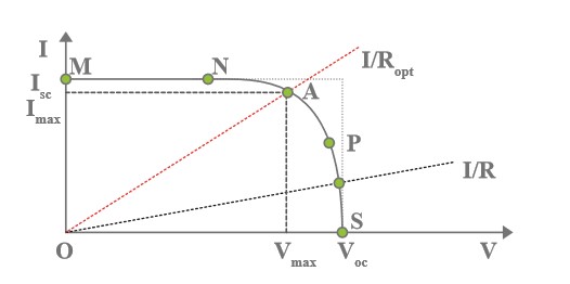
Figure 8- I-V curve of a solar cell
The simplified I-V curve of a solar cell is demonstrated in Fig. 8. As it is illustrated, for small resistance, the solar cells operate between M and N points while for higher resistance the system operates between P and S points of the mentioned curve. The area under the curve counts for power transformed into a PV system (P=V×I
P=V×I). This area is maximum when the curve is on A point in which the system reaches the optimum energy transfer, so it should be noted that for other points the system will have a power loss. The A point is also called a maximum power point.
Fill factor (FF) which is introduced below is a measure of efficiency in the PV systems, for an efficient solar cell this factor should be more than 0.7. Note that temperature increment leads in FF reduction.
FF=Imax VmaxIsc Voc
FF=Imax VmaxIsc Voc
To avoid this power loss charge controllers are employed in PV systems. For example, MPPT controllers find the optimum point and track it by current or voltage regulations. If the voltage of the solar cell is too low, the system will have noticeable power loss due to the supplied voltage which is illustrated in Fig. 9. Similar power loss would happen due to low current flow which should be controlled by the charge controller.
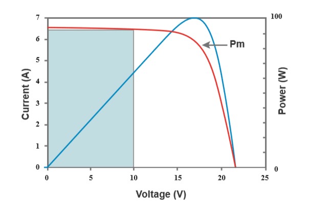
Figure 9- power loss due to the low voltage level
Now it’s time to discuss MPPT and PWM charge controllers and their behavior regarding the I-V curve of a solar cell. The blue line demonstrated in Fig. 10 is the power transmission in a solar cell. It can be noted that the optimum point in the red line which belongs to optimum voltage and current, leads to the maximum power transfer. So an efficient charge controller should track this point and related maximum power. For an MPPT charge controller with a constant battery voltage, the controlling algorithm will increase the current of the solar cell until the power reaches the maximum amount.
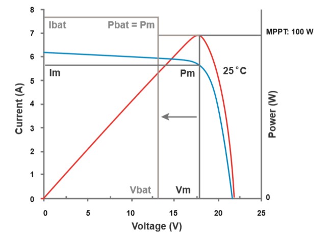
Figure 10-I-V curve of the MPPT charge controller
For fixed voltage level MPPT controller increases the current until the product of new voltage and current levels get closer to maximum power which is 100 watts. By this controller with any voltage level and with the help of DC/DC converter, maximum power transfer can be achieved.
In the case of PWM controllers, the voltage of the panel and the battery are also the same and a minor voltage loss due to the connecting cables and accessories can be noticed. In such controllers, voltage and current of the PV system are determined by a vertical line on the I-V curve. For the mentioned 13V battery, the amount of power transmission based on the I-V curve of the PWM charge controller will be around 81 watts. The power loss compared to the maximum power will be 19% in this controller, while PWM is not a DC/DC converter, cannot increase the amount of current to achieve the maximum power transmission despite what MPPT charge controller does.
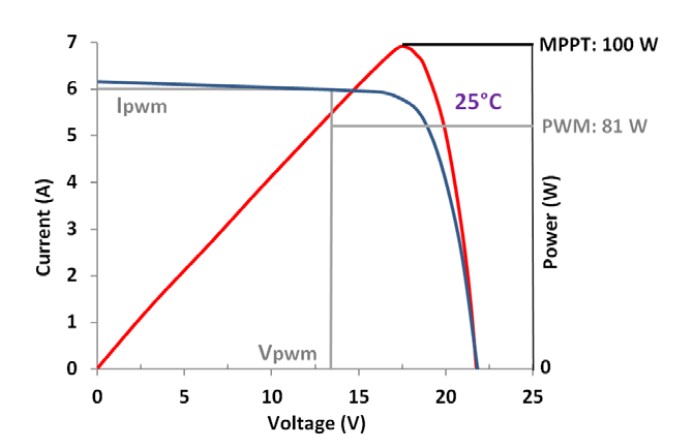
Figure 11- I-V curve of the PWM charge controller
Multi-stage charging
Most of the MPPT charge controllers have a “Multi-stage charging” functionality. Here we discuss each. The whole process is demonstrated in Fig. 12.
BULK charging: is the stage in which the controller will harvest maximum energy from the PV panel. At this stage, the MPPT controller will work at Vmpp, while for PWM controller, the PV voltage will remain at battery voltage.
Constant charging: when the battery voltage reaches the constant voltage set point, the controller will start to operate in constant charging mode, this process is no longer MPPT charging, and in the meantime, the charging current will drop gradually. For the PWM controller, the duty cycle will not be 100%, and the PV voltage will fluctuant along with duty cycle and the charging frequency.
The Constant Charging has 2 stages, equalize and boost. These two stages are not carried out constantly in a full charge process to avoid too much gas precipitation or overheating of the battery.
Float charging: After the Constant voltage stage, the controller will reduce the charging current to the Float Voltage set point. This stage will have no more chemical reactions and all the charge current transforms into heat and gas at this time. Then the controller reduces the voltage to the floating stage, charging with a smaller voltage and current. This will reduce the temperature of the battery and prevent the gassing while charging the battery slightly at the same time. The purpose of the Float stage is to offset the power consumption caused by self-consumption and small loads in the whole system while maintaining full battery storage capacity.
In Float charging stage, loads are able to obtain almost all power from the solar panel. If loads exceed the power, the controller will no longer be able to maintain battery voltage in Float charging stage. If the battery voltage goes down below the Recharge Voltage, the system will leave the Float charging stage and return to Bulk charging stage.
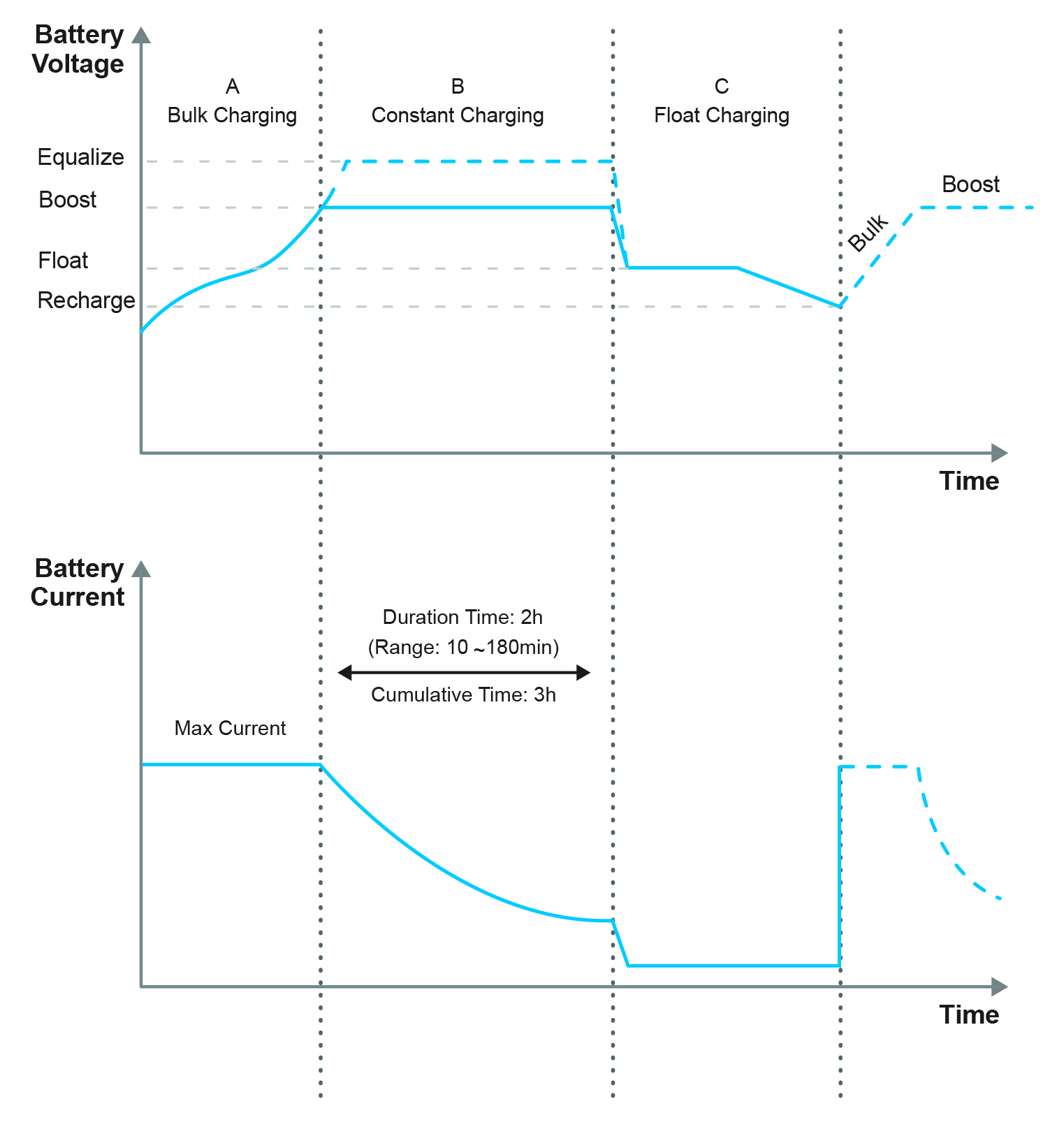
Figure 12- I-V curve of the PWM charge controller
Temperature Effect
The sun shining on the solar panel causes temperature increment in the PV system. As discussed in previous sections, I-V characteristics of solar cells mainly depend on environmental conditions such as temperature. The efficiency of PV systems is a function of temperature, such that as the temperature of the solar panel increases the efficiency diminishes. I-V curves for different temperatures demonstrate that open-circuit voltage of solar panel changes by the system temperature. In fact open-circuit voltage shift toward lower levels. Maximum power of the PV system is also affected by temperature, where current level stays the same by various temperature conditions. Constant short-circuit current amount with lower open-circuit voltage will provide a lower power level. This phenomenon plays a key role in the design of solar cell systems and cooling equipment to consider environmental conditions. Both MPPT and PWM charge controllers suffer from efficiency reduction in high-temperature cells, but the solution of this problem is providing more series solar cells in array structure which enhances the level of open-circuit voltage and compensates power loss due to high temperature. This solution is not proper for low temperatures. It should be noted that this method is not applicable in the case of PWM charge controllers. For example, to provide a 24V/100W panel, we can add two 12V/100W panels in series.
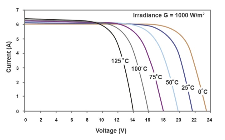
Figure 13- temperature effect on I-V characteristics of solar cell
To compare the performance of PWM and MPPT controllers in different temperatures, an experimental test has been done by a setup of both controllers.
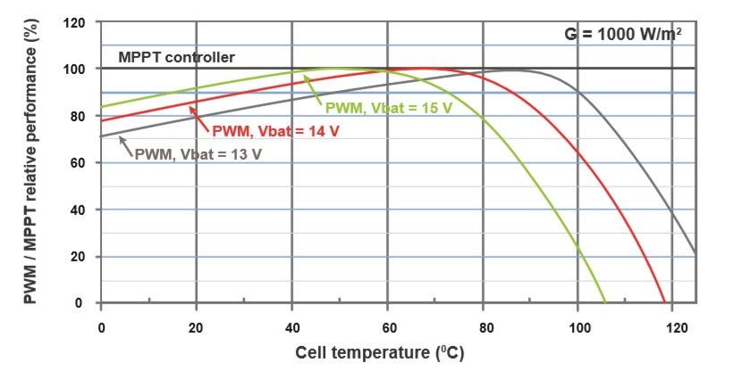
Figure 14- performance of PWM and MPPT controllers in different climate conditions
Fig. 14 illustrates the effect of temperature, which MPPT is set to 100% in every temperature condition by the application of MCU on its structure which senses the temperature of the panel and sets the voltage and current inquiries. PWM charge controllers act as switches to connect or disconnect the panel to the battery so they cannot track or sense the temperature to compensate the power loss.
Pros and cons
In this section both PWM and MPPT, charge controllers’ operation will be compared. Advantages and disadvantages of both controllers are discussed here. The comparison of their performance will help the client to select the proper controller. The PCB of both charge controllers is also demonstrated in Fog.15 which shows that MPPT is more complex than the PWM charge controller which explains why MPPT charge controllers are expensive ones.
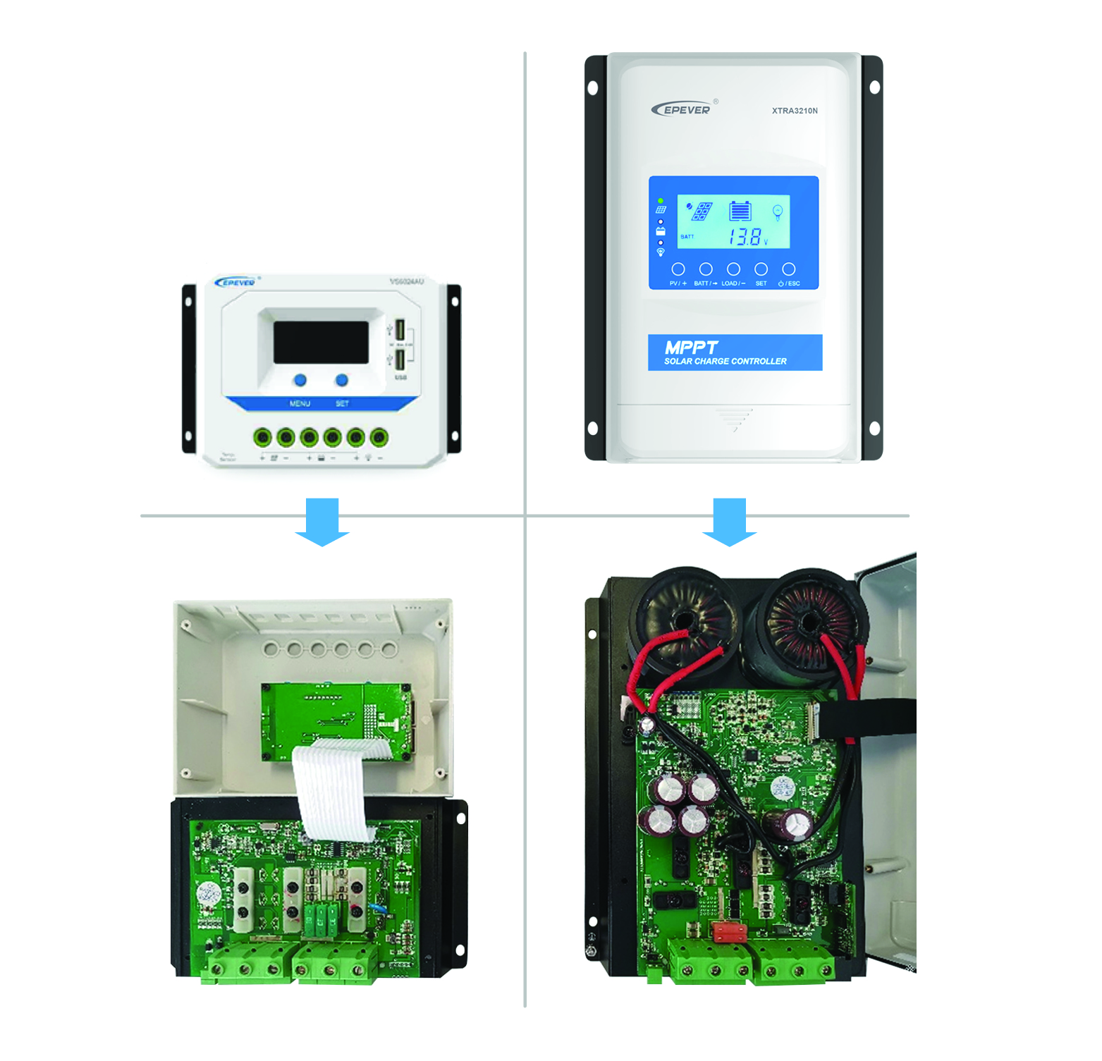
Figure 15-PCB and internal circuits of PWM and MPPT charge controllers
Solar Charge Controllers
| PWM Charge Controller | MPPT Charge Controller |
|---|---|
| Support 3 charging options: Sealed, Gel, and Flooded | Fast-tracking speed |
| 3-Stage Intelligent PWM charging: Bulk, Boost/Equalize, Float | Full load transfer efficiency up to 97.4% |
| Terminals have UL and VDE certification, the product is safer and more reliable | Low-temperature protection |
| Energy statistics function | Comprehensive electronic protection |
| Battery temperature compensation function | Dustproof and waterproof design |
| Extensive Electronic protection | Over-temperature protection |
| Multiple load control modes | Monitor and set the parameters via the APP or PC software |
| Double USB design, the power supply charge for electronic equipment | High quality and low failure rate components of ST or IR to ensure the service life |
| The controller can work continuously at full load within the environment temperature range from -25 to 55 ℃ | Multiple load work modes |
Technical specifications of both charge controllers are discussed on EPEVER product catalogs which are available on www.epsolarpv.com
| PWM Charge Controller | |
|---|---|
| Pros | Cons |
| Doesn’t have any mechanical switches or connections | Suboptimal power output at low and very high solar cell temperatures. |
| Low-cost setup and design | Degrading output power in rainy or heavily clouded days |
| Good performance for moderate-high temperatures 45-75°C | Noise problems due to the sharp pulses |
| The proper choice for small systems, where the efficiency of the system is not critical | Performance reduction in large arrays where more energy harvesting is worthwhile |
| MPPT Charge Controller | |
|---|---|
| Pros | Cons |
| Little power loss | The expensive choice for small systems |
| Smart DC/DC voltage converter | Regular calibration due to the more electronic components |
| Smart tracking for optimum energy transfer | |
| Temperature compensation algorithm | |
| Proper performance at low and very high solar cell temperatures | |
| A suitable choice for large arrays to decrease the cable and connections’ cost | |
For solar panels with more than 32 cells, an MPPT charge controller is usually required, since PWM charge controllers harvest the same energy from 36, 40, 44 cell panels as the 32 cell panel. So it can be concluded that for small PV systems with moderate climate conditions, PWM charge controllers are the proper choices but for large systems which require high-efficiency applications, MPPT’s are the best choice. They can also act on low and very high-temperature climate conditions by the help of smart current compensation.
I have a Tracer 4210A
I want to use it in my RV.
My devices are DC, Can I use Load output port for driving those devices? some one told me I can not use the load port for my devices, (I know for Inverter I must use Battery directly) My question is about DC devices.
If I can, what is the limitation of output amp?
I read the user manual but I can realize it.
What does “Maximum Discharge Current” number mean? Is it the maximum current that can be drawn from the Load output of the charge controller?
caratteristiche e listini regolatori di carica PWM e MPPT con minimi spedizione a 28845 Domodossola (VB) Italia
Ringrazio e saluto. Giorgio Pignagnoli
Hi Pignagnoli, thanks for your trust. Please drop an email to info@epever.com, our colleagues will contact you asap. You can learn EPEVER MPPT&PWM controller here: https://www.epever.com/products/?yith_wcan=1&product_cat=charge-controller